Functional Safety in Tunnel Ventilation Control Systems
What is Functional Safety in a TVCS Context?
IEC 61508 provides a risk-based lifecycle for electrical, electronic and programmable electronic safety-related systems. In a rail project, it should be applied within the project's broader Reliability, Availability, Maintainability and Safety (RAMS) framework, together with applicable fire, life-safety and authority requirements. A Safety Integrity Level (SIL) is allocated to a specific safety function through hazard and risk assessment; it is not a blanket rating applied to every TVCS panel or device.
For each safety function, the Safety Requirements Specification should define the initiating condition, system boundary, demand mode, response time, required safe outcome, operator actions, reset philosophy, interfaces, environmental assumptions and proof-test requirements. Clearly defining these requirements early helps prevent ambiguity during detailed design, FAT, SAT and lifecycle maintenance.
How Should a TVCS Safety Function Be Defined?
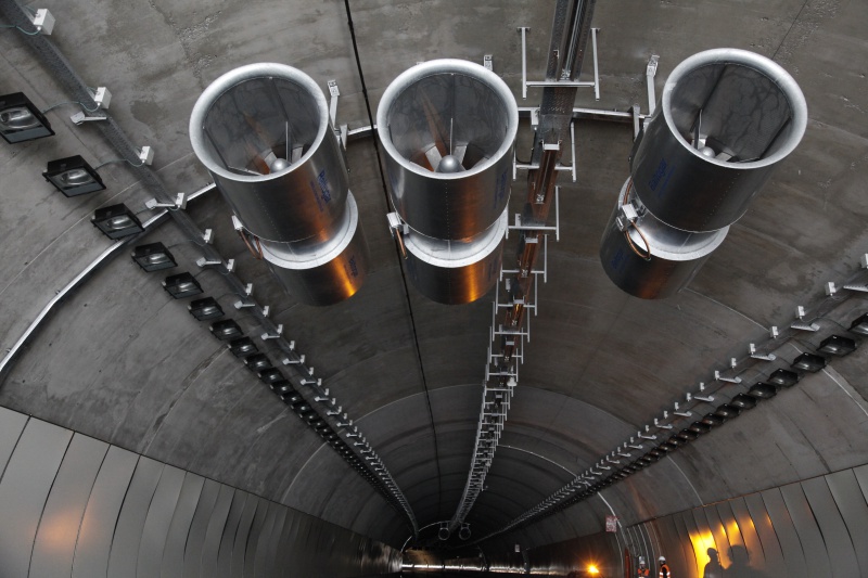
Practical experience from a metro TVCS arrangement showed that failure or unavailability of a critical damper associated with the duty Tunnel Ventilation Fan (TVF) should prevent that fan from being declared available. Subject to the approved cause-and-effect strategy, duty may then transfer automatically to the designated standby TVF, but only after verifying the health of the fan, power supply, protective devices and associated dampers, and confirming that the required airflow path is available. This capability is important where a TVF may be unavailable because of maintenance or mechanical faults.
If no healthy alternative was available, the system entered its defined degraded mode and clearly alerted the operator. A safe state in a TVCS does not necessarily mean switching off all equipment. During a tunnel fire, stopping every fan could allow smoke to spread into evacuation or firefighting routes. In that metro arrangement, the fans, dampers and emergency operating modes were interlocked according to predefined safety scenarios. The safety modes for each station or annex were also available from a local Backup Control Panel (BCP) in the Station Master's Room. This provided an authorised local means of operating the required safety mode if control from the higher-level system was unavailable. The correct safe state was therefore a scenario-specific ventilation configuration supported by an appropriate control fallback, not a universal shutdown.
What Does SIL 2 Actually Require Across a TVCS?
- Architecture and Independence: A redundant PLC arrangement should not be considered safe solely because two controllers are installed. If both controllers depend on the same power supply, network switch, communications path or cabinet environment, a single common-cause failure could defeat the redundancy. The required independence, segregation and hardware fault tolerance must be justified through the safety requirements, reliability calculations and SIL verification.
- Diagnostics and Final Elements: Diagnostics must extend beyond PLC health. The design should monitor command/feedback discrepancies, damper end positions, fan and VSD status, protective-device trips, power availability and communications quality. A successful PLC output command does not prove that the fan has started or that the required airflow path has been established.
- Deterministic Software: Implement clear, state-based sequences derived from an approved cause-and-effect matrix. Define transition conditions, timeouts, fallback actions, latching, reset and first-out indication. Command priority between automatic emergency modes, SCADA, the Backup Control Panel and local controls should also be clearly defined and tested.
- Power and Communications: The availability of emergency power, network failures, validity of interface data and restart behaviour must be considered as part of the end-to-end safety function. The system should have a defined response to the loss of a field network, remote I/O, MCC or final element, including the required fallback or degraded mode, operator alarm and recovery behaviour. A SIL-capable controller cannot compensate for an undefined response elsewhere in the control chain.
How Should TVCS FAT and SAT Testing Be Structured?
Use one controlled cause-and-effect model to align fire scenarios, operating modes, control narratives, HMI behaviour, PLC logic and test scripts. Verification should be independent and evidence-based: requirements reviews, architecture checks, software reviews, requirements traceability and safety calculations are as important as functional demonstration.
FAT and SAT should extend beyond I/O loop checks, normal sequence testing and basic functionality demonstrations. Testing should deliberately create credible failure conditions and observe the complete system response. Examples include a critical damper failing to reach position, the duty TVF failing to start or tripping during operation, the standby TVF being unavailable, loss of communication with an MCC or remote I/O panel, controller, power-supply or network-switch failure, contradictory field feedback, alarm flooding, interruption of an active emergency sequence, and loss and restoration of power. Testing should verify automatic fallback, response time, alarms, HMI and BCP indications, operator actions, reset behaviour and recovery to a controlled state.
Maintainability must also be designed into the system. Proof-test procedures, bypass controls, impairment management, diagnostic coverage, spares availability, firmware compatibility and obsolescence planning determine whether the claimed safety integrity can be sustained after handover.
What Goes Wrong During TVCS Power-Cycle Recovery?
Brownfield tunnel work repeatedly shows that latent problems appear during transition, not during steady operation. Experience from a metro TVCS upgrade showed how a communication-module and battery-related anomaly became significant during power-cycle recovery even though normal runtime operation appeared stable. The lesson was simple: restart, recovery and restoration tests deserve the same attention as the emergency sequence itself.
Why Interface Ownership Fails on Multi-Vendor TVCS Projects
Interface ownership is another recurring challenge. Fire detection, power, fan packages, dampers, station systems and SCADA may be supplied by different parties. A precise interface register, clear signal-quality definitions and witnessed end-to-end testing help expose assumptions that individual subsystem tests may miss. For tunnel and rail assets, an early installed-base survey also prevents legacy limitations from being discovered only when commissioning windows are already constrained.
Key Design Requirements for SIL 2 TVCS
- Assign SIL to clearly defined safety functions, not to the TVCS as a general product label.
- Define safe state, response time, mode priority and degraded behaviour for each credible scenario.
- Design diagnostics and validation around the complete sensor–logic–final-element chain.
- Prove power-cycle recovery, communications loss and partial-sequence failures during FAT and SAT.
- Protect lifecycle integrity through maintainable proof tests, controlled change and long-term asset support.
Standards and Further Reading
- IEC, Overview of functional safety and the IEC 61508 lifecycle — iec.ch/functional-safety
- Australian Transport Safety Bureau, Safety Issue RO-2018-014-SI-01 — System Safety Assurance for Australian Rail — atsb.gov.au/safety-issues/RO-2018-014-SI-01